|
Skylite User Manual
for
High Frequency
Electrodeless
Fluorescent
Lamp
I.
Installation Dimensions
(A)
Drill pattern of power coupler mounting flange
(B)
Dimensions of HF Electronic Ballast

II. Wiring Diagram
As shown in figure above:
HF output wire of the bulb can not be pressed, twitched
or folded.
The user can not change the length of the cable.
Short-circuit of interior or exterior of the wire can
cause the damage of the lamp system.
Power supply wiring _ AC 220V, 2A (ampere)
cable_ (L & N)
The power supply wiring is the electrical connection
between the power supply and the electronic ballast
input.
This wiring must always use a 3-core cable for phase,
neutral and grounding connections.
The phase and neutral of the power supply must be
connected to the connector block as described on the
housing label.
HF output wiring
This wiring must be via the coaxial cable that is
supplied as standard with the power coupler.
Connections to the HF output of the HF electronic
ballast must be made according to the color-coding of
wires and the connector block.
The white wire must be connected to the +pole, and the
black wire to the -pole.
Changing or extending of the coaxial cable is never
allowed.
As shown in figure above:
The bulb, HF electronic ballast and fixture must always
be grounded separately.
III. Tips for Thermal Conductivity and Resistivity
Ø
Keep the mounting flange of the power coupler at
non-contact position of 20mm distance away from the HF
electronic ballast for heat assistant reason.
Ø
Ensure good heat transport to the surroundings (heat
sinking).
Ø
Use separate heat sinks for both the power coupler and
HF electronic ballast.
Ø
Avoid heat radiation from lamp to HF electronic ballast.
Ø
Mount the bottom of the HF electronic ballast housing on
its own heat sink; but never apply a heat sink for the
test point only.
Ø
Create a cooling airflow
IV.
Caution
●
Combination of a lamp, a power coupler and a HF
electronic ballast; all with the same wattage
indication.
●
Only system components with the same wattage indication
(100W or 130W or 160W or 200W) may be combined! Any
other combination might cause damage to the lamp system
components.
●
Every HF electronic ballast may only be combined with
one lamp/power coupler set of the same wattage; failure
to observe this basic rule might cause damage to
lamp system components.
●
Ensure firm electrical contact between all metal parts,
the ballast housing and power coupler as well as correct
wiring connection before turning on the power.
●
Spec. of the power supply wiring: bearing capacity - 2A
current and 0.75mm2 x 3C (ground wire included).
●
Ambient Temperature: -10℃~+40℃
●
For your safety, turn off the power before installation.
●
If an abnormal condition exists, turn off the power and
ask professional electrical technician for assistance.
Do not disassemble or attempt any repairs by yourself.
●
We are not responsible for any damages caused from
improper fixture that is not provided or approved by us.
●
Do not light on the naked lamps (that means bulb and HF
electrical ballast only) without assembling with
fixtures over 15 minutes.
●
To prevent scald, do not touch the bulb when it is
working.
●
Naked lamp can’t be assembled with the fixture of no
heat-dissipation device.
●
Use only our components to retrofit our EFL when
necessary.
●
The
–pole
of HF electronic ballast output is not earth wire. Do
not use any measuring machine to do any test.
●
No colliding!!
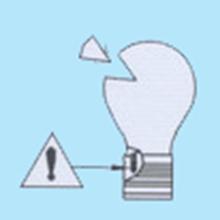
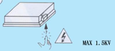
●
Risk
of electric shock. No Touching!!
●
If the bulb shows red light and then turns off when the
power is on. That means the bulb is damaged.
●
Warranty void if seal damaged.
|